The Basic Principles Of Wedge Barriers
Wiki Article
Wedge Barriers Can Be Fun For Everyone
Table of ContentsExcitement About Wedge BarriersThe Wedge Barriers Diaries
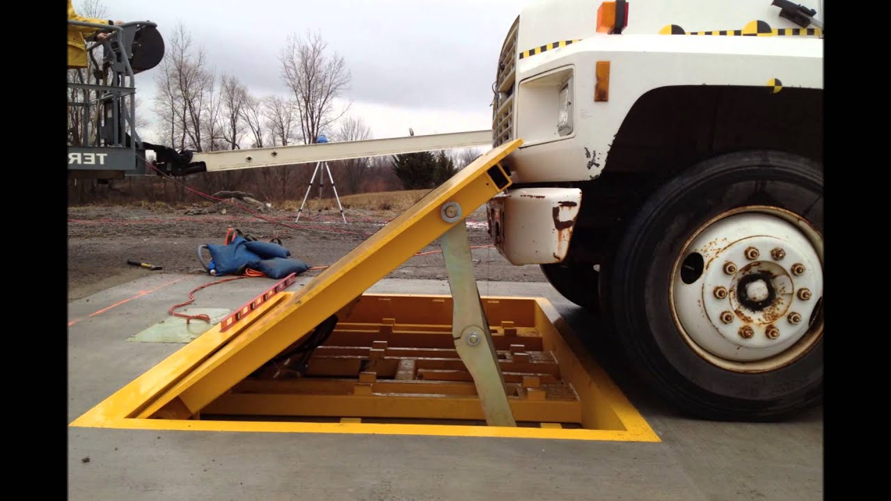
14 and the surface area 12 to which the barrier 10 is protected might be made from concrete - Wedge Barriers. 2, the obstacle 10 is placed to or includes a support or subframe (e. g., anchor 30 received FIG. 2 )protected beneath the surface 12. The bather 10 may be bolted to the support or safeguarded to the anchor by various other mechanical bolts. In the illustrated embodiment, the obstacle 10 consists of a wedge plate 16, that includes a section that is substantially parallel with the surface 12 when the obstacle 10 remains in the withdrawed position. Simply put, automobiles or individuals might pass over the barrier 10 when the obstacle 10 is in the withdrawed position and experience small altitude about the surface area 12 while on the obstacle 10. As discussed thoroughly below, when the barrier 10 is in the released placement, the wedge plate 16 is held and sustained in a raised position by a lifting system of the barrier 10. In addition, the components 18 may be bolted or otherwise mechanically paired to each other. In this way, fixing or substitute of one or more components 18 may be simplified and structured. That is, fixing or substitute of solitary elements 18 might be done quicker, conveniently, and price effectively. FIG. In certain embodiments, the anchor 30 might be a steel structure consisting of plates, light beams(e. g., I-beams ), and/or other structures that are safeguarded within the foundation 14, which may be concrete. At the surface 12, an upper side 28 of the support 30 may be at the very least partly revealed , therefore allowing the add-on of the barrier 10 to the anchor 30. g., threaded openings)in one or more beam of lights or plates of the anchor 30 might be subjected to the surface area 12. In this fashion, bolts 32 or other mechanical bolts might be used to secure the obstacle 10 to the support 30. As the barrier 10 is mounted to the surface area 12 of the foundation 14, collection of particles and other product under the barrier may be lowered, and elements of the bather 10 might not be revealed to below quality atmospheres. As indicated by referral character 52, the training device 50 consists of parts disposed underneath the wedge plate 16. For instance, the elements 52 below the wedge plate 16 may consist of an electromechanical actuator, a camera, several camera surface areas, and so forth. Furthermore, the training device 50 review includes a springtime setting up 54
The spring rod 58 is coupled to a cam(e. g., webcam 80 displayed in FIG. 4) of the lifting system 50. The springtimes 60 disposed about the spring pole 58 are held in compression by spring supports 62, including a fixed spring assistance 64. That is, the set spring support 64 is dealt with about the structure 14 et cetera of the bather 10.
The smart Trick of Wedge Barriers That Nobody is Talking About
The staying pressure applied to the cam webcam deploy release wedge plate 16 may might provided by an electromechanical actuator 84 or other actuator. The spring setting up 54 and the actuator 84(e. Wedge Barriers. g., electromechanical actuator)may operate together to convert the cam and lift the wedge plate 16.
As stated over, the springtime assembly 54 puts in a continuous force on the camera, while the electromechanical actuator might be managed to exert a variable pressure on the camera, thus making it possible for the training and decreasing( i. e., deploying and retracting )of the wedge plate 16. In certain embodiments, the consistent pressure applied by the springtime setting up 54 may be flexible. g., electromechanical actuator) is handicapped. As will certainly be valued, the spring setting up 54 may be covered and protected from particles or various other elements by a cover plate(e. g., cover plate 68 displayed in FIG. 4) that might be substantially flush with the elevated surface area 38 of the structure 14. As stated above, in the released position, the wedge plate 16 offers to obstruct access or traveling past the barrier 10. The obstacle 10(e. g., the wedge plate 16 )might obstruct pedestrians or cars from accessing a home or pathway. As talked about above, the barrier 10 is attached to the anchor 30 safeguarded within the structure 14,
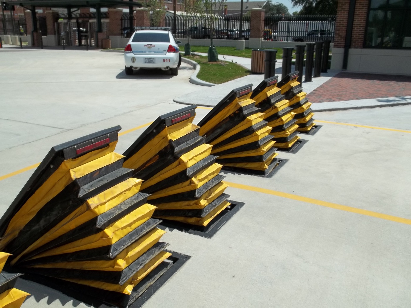
front braces 71. As a result, the linkage assemblies 72 might pivot and turn to allow the collapse and extension of the affiliation settings up 72 during retraction and release of the bather 10. The affiliation assemblies 72 reason movement of the wedge plate 16 to be restricted. If an automobile is traveling in the direction of the deployed wedge plate 16(e. For example, in one situation, the safety and security legs 86 may be expanded throughoutmaintenance of the barrier 10. When the safety and security legs 86 are deployed, the safety legs 86 sustain the weight of the wedge plate 16 against the surface 12. Therefore, the training mechanism 50 may be shut down, serviced, eliminated, changed, etc. FIG. 5 is partial perspective view of an embodiment of the surface-mounted wedge-style barrier 10, highlighting the camera 80 and the web cam surfaces 82 of the training device 50. Specifically, 2 camera surface areas 82, which are referred to as lower webcam surfaces 83, are positioned listed below the cam 80. The lower web cam surface areas 83 might be repaired to the surface area 12 (e. As an example, the lower webcam surfaces 83 and the placing plate 85 might form a solitary piece that is safeguarded to the anchor 30 by bolts or various other mechanical fasteners. Additionally, two webcam surface areas 82, which are described as top web cam surface areas 87, are positioned over the webcam 80 and paired to (e. In various other personifications, interfering layers or plates might be placed in between the surface area 12 and the reduced web cam surface areas 83 and/or the wedge plate see 16 and the top webcam surfaces 87 As discussed above, the cam 80 equates along the cam surface areas 82 when the wedge plate 16 is raised from the retracted placement to the deployed placement. Furthermore, as pointed out above, the spring assembly 54 (see FIG. 3 )might provide a pressure acting upon the cam 80 in the instructions 102 through springtime pole 58, which may lower the force the electromechanical actuator 84 is required to put on the camera 80 in order to actuate and lift the wedge plate 16. 1 )to the released setting(see FIG. 4). As shown, the webcam 80 consists of track wheels 104(e. g., rollers), which call and equate along the camera surface areas 82 during procedure.
Report this wiki page